| Application of thermal conductive interface material and forced air cooling in e |
| Release time:2023-03-03 08:50:08| Viewed: |
In the power grid system, the production and consumption of electricity need to keep pace. However, due to the intermittent and random disadvantages of wind power and photovoltaic power, their power generation status is unstable and uncontrollable, and they cannot be stored on a large scale.
The large-capacity energy storage technology can not only smooth the power fluctuation of wind power and photovoltaic power, promote its large-scale absorption and access, but also carry out frequency modulation and peak regulation on the power grid, improve the ability of safe and stable operation of the power grid, which clears the obstacles for the large-scale development of wind power and photovoltaic power.
The research results show that in some medium-high magnification application scenarios, the heat conduction interface material and forced air cooling can be used to cool the heat; The filling effect of the good thermal conductivity interface material can improve the heat dissipation capacity of the lithium-ion battery module, which can provide a theoretical basis for the design of the thermal management system of the energy storage battery module.
1. Heat dissipation mode of energy storage module
As the energy carrier of the container-level energy storage power station, the research and development of the large-capacity battery module includes the following key technologies: system integration technology, structural design technology, electronic and electrical design technology, thermal design technology, and safety design technology.
Among them, thermal design technology is a critical step in the development of large-capacity energy storage battery modules. The temperature of the battery and the temperature uniformity between the individual cells in the PACK are the key factors that affect its performance and life. Therefore, a good thermal management strategy can effectively control the maximum temperature of the battery, ensure that the battery is within the appropriate temperature range, balance the temperature between the cells, and provide a strong guarantee for the efficient, safe and long-life operation of the energy storage battery.
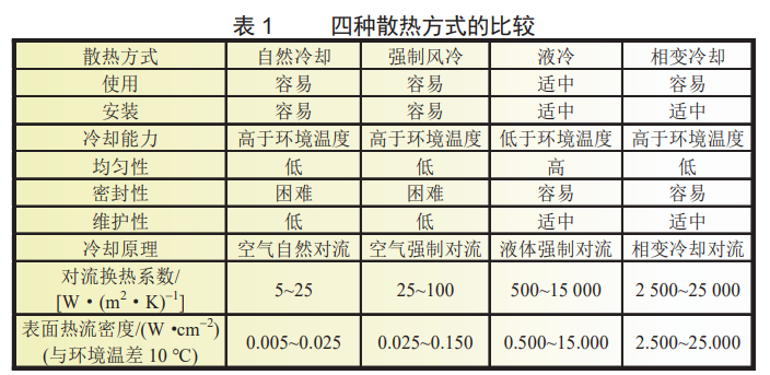
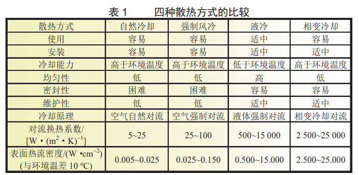
According to the different heat transfer media, the cooling methods of the battery module can be divided into natural cooling, forced air cooling, liquid cooling and phase change cooling.
The basic principle of the three cooling methods of natural cooling, forced air cooling and liquid cooling is that the cooling medium flows through the surface of the heating body. Because of the difference in temperature between the two, the heat of the heating body is carried away by the heat transfer between the two, and the cooling medium does not change phase during this process;
It can be seen from Table 1 that liquid cooling and phase change cooling are significantly higher than natural cooling and forced air cooling in terms of cooling capacity and cooling efficiency. However, considering the battery charging and discharging conditions, environmental conditions, product structure design, power consumption and cost requirements, natural cooling and forced air cooling are more suitable for energy storage battery modules.
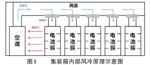
This is due to the fact that air-cooled air conditioners and corresponding air duct designs are generally equipped in the square cabin energy storage system. After the air conditioner operates, cold air will continuously enter the battery box through the special air-cooled channel to take away the heat released by the battery charging and discharging, and the heated air will also be sucked into the air conditioner with the operation of the air conditioner, as shown in Figure 1.
In this way, the hot and cold air cycle alternately, and the ambient temperature inside the cabin is reasonably regulated to ensure that the battery is in a suitable environment. At the same time, through the open air conditioning communication protocol, the temperature of the battery is used to control the start and stop of the air conditioning, so as to realize the efficient and energy-saving air conditioning operation scheme.
2 .Heat dissipation and conduction scheme of energy storage module
Under low magnification conditions, the heat emitted during battery charging and discharging can be taken away by the natural flow of air. However, in some medium-high magnification products, due to the large charging and discharging current, the heat inside the module can not be quickly and effectively dissipated only by natural cooling, which is very easy to cause the accumulation of heat inside, thus affecting the cycle life of the battery core, and even causing safety hazards. Therefore, forced air cooling is more suitable for the application scenario of medium-high rate energy storage products.
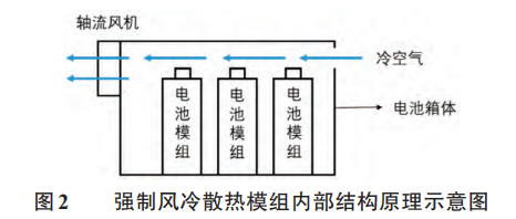
The internal structure of the forced air cooling cooling cooling module is generally shown in Figure 2: an axial flow fan is installed on the front panel of the sheet metal battery box, and several battery packs are located at the bottom of the box in turn inside the battery box, and a grid shaped ventilation hole is designed at the top of the rear of the box.
After the axial flow fan operates, the cold air enters the box through the rear grid shaped ventilation hole, and sweeps through the surface of the bus bar on the top of the battery pack in turn. The bus bar and the electric core pole are welded together by laser, and the position of the electric core pole during the charging and discharging process is the current gathering place, which is also the most serious heating area.
In addition, the bus bar is generally made of aluminum or copper, both of which are good conductors of heat. The thermal conductivity of pure aluminum is 237 W/(m · K), and that of pure copper is 401 W/(m · K).
Therefore, as the cold air sweeps over the bus, the heat at the pole end will be dissipated into the air with the bus as the medium, and with the flow of air, it will be finally pumped to the outside of the box by the fan, so as to realize the internal cold and heat exchange.
Under some more severe working conditions, the heat dissipation at the battery pole end can no longer meet the use requirements, and other heat dissipation methods need to be supplemented to improve the overall heat dissipation efficiency of the system. Therefore, we take the battery bottom as another auxiliary heat dissipation interface of the system for relevant design.
The battery pack is usually directly located at the bottom of the box, and the box is mostly made of cold-rolled steel plate, which is also a good conductor of heat. Through the contact between the bottom of the battery and the box, the heat inside the battery is transferred to the surface of the box, and then through the heat exchange between the surface of the sheet metal box and the external environment, the purpose of auxiliary heat dissipation at the bottom of the battery can be achieved.
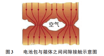
However, in the actual assembly process, the slight unevenness at the bottom of the battery pack and the factors of the flatness error at the bottom of the box will cause the close contact between the battery pack and the box, that is, there will be a small air gap between the battery pack and the bottom of the box. Air is a poor conductor of heat, and the air gap will increase the thermal resistance between the battery pack and the box, affecting the heat dissipation effect, as shown in Figure 3.
In order to solve this problem, it is urgent to find a solution that can fill the gap between the two contact planes, reduce the thermal resistance of the target element to the environment, create a convection path with low thermal resistance between the bottom of the battery and the box, and ensure uniform contact and high heat transfer efficiency.
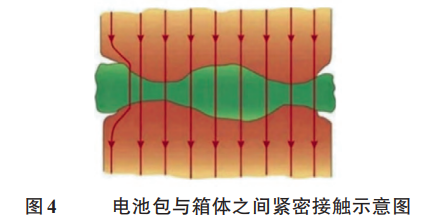
In many schemes, the thermal conductivity interface material has the advantages of high thermal conductivity and low interface thermal resistance. At the same time, its high deformation and good compressibility enable it to eliminate the air between the contact surfaces under a certain pressure and fully fill the rough area between the contact surfaces, so as to improve the thermal conductivity between the contact surfaces. Its good filling performance can transfer the heat from the heating end to the cooling end, as shown in Figure 4.
Thermal conductive interface materials have two different forms, solid and liquid, which can meet the requirements of product performance diversification.
Liquid thermal conductive interface materials generally include thermal conductive paste, thermal conductive adhesive, etc. These thermal conductive materials in liquid form can be directly applied to the target components as the adhesive with the radiator. At the same time, these materials can also be mixed with ceramic fillers, metal or metal oxide fillers to obtain high thermal conductivity.
(2) Thermal conductive silicone gasket
The thermal conductive silicone gasket is a kind of thermal conductive interface material synthesized by a special process with silicone as the main substrate, adding various auxiliary materials such as temperature resistance, thermal conductivity and insulation materials.
Unlike liquid thermal conductive materials, the preformed solid thermal conductive silicone gasket is also very simple to use, and can be die-cut according to the required size, which is suitable for connecting with the radiator on the plane element or directly attaching to the shell. The pasting of thermal conductive silicone gasket can be integrated with the automatic assembly process, further improving the production efficiency and automation.
3 .Experimental verification
Considering the flexibility of the assembly of the energy storage module and the subsequent maintenance operation, the research team finally selected the thermal conductive silicone gasket as the thermal conductive interface material to fill the gap between the battery pack and the box, with a thermal conductivity of 2 W/(m · K) and a thickness of 1 mm.
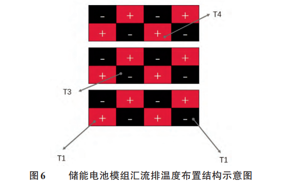
In order to monitor the temperature change during battery charging and discharging in real time, a temperature sensor is set on the busbar at the position shown in Figure 6, and the temperature of the busbar is detected by the battery management system (BMS).
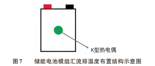
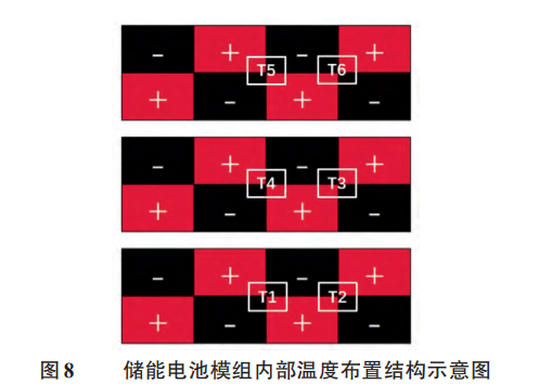
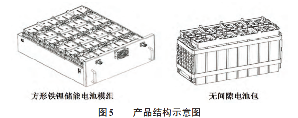
Because the battery pack adopts a gapless structure, the adjacent cells are almost close to each other, resulting in poor heat dissipation conditions inside the battery pack. In order to more fully reflect the temperature inside the battery pack, a thermocouple temperature monitoring point is added between the cells at the specified location, and the location of the thermocouple pasted on the cell is shown in Figure 7.
Fix the K-type thermocouple with high temperature tape in the area near the center of the contact surface between the core and the core. During the test, connect the thermocouple with the data collector to monitor the temperature of the contact area between the core and the core in real time during the charging and discharging process.
A total of 6 thermocouple temperature sampling points are arranged inside the battery pack, as shown in Figure 8.
In order to compare and analyze the heat dissipation effect of heat conduction gasket, two experiments are designed as shown in Figure 9 for comparison. On the premise that the other conditions are completely the same, the three battery packs in Scheme 1 are in direct contact with the sheet metal box, and the three battery packs in Scheme 2 are added with a thermal conductive silicone gasket with a thermal conductivity of 2 W/(m · K) and a thickness of 1 mm between the three battery packs and the box.
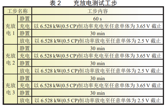
At an ambient temperature of 25 ℃, the test steps in Table 2 are used for the experimental scheme shown in Figure 9, and three charge-discharge tests are carried out.
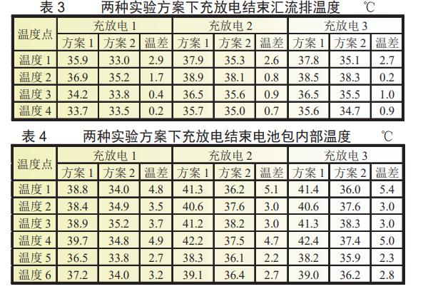
At the same time, record the internal temperature of the busbar and battery pack after each charge and discharge, and obtain Table 3 and Table 4.
4 .Conclusion
The purpose of this paper is to explore and analyze the application effect of thermal conductive silica gel gasket in large-capacity square iron lithium battery module by using two schemes for comparative test.
From the test data of Scheme 1 and Scheme 2, it can be seen that there is no significant difference between the temperature of the bus collected by BMS, while the temperature inside the battery pack shows different characteristics. The temperature inside the battery pack in Scheme 2 is significantly lower than that in Scheme 1.
It is concluded that adding heat conductive gasket can improve the heat transfer rate between the battery pack and the box, effectively transmit the heat accumulated inside the battery pack to the outside, and thus reduce the temperature inside the battery pack.
|


